MFR-7 Multifilter Rotating Shadowband Radiometer
 The Multifilter Rotating Shadowband Radiometer (MFR-7) measures total, diffuse, and direct irradiance at six wavelengths (415, 500, 615, 673, 870, and 940 nm, each 10 nm FWHM) in the visible/NIR, and includes one unfiltered broad-band silicon pyranometer. Thermally stabilized, environmentally sealed state-of-the-art interference filters provide excellent long term calibration stability. Instead of using a rotating filter wheels the MFR-7 makes measurements simultaneously across all seven channels, meeting the Baseline Solar Radiation Network's requirements for atmospheric turbidity measurements. The shadowband enables the instrument to measure all three components of solar irradiance with one detector. The MFR-7 system includes the YESDAS-2 datalogger and works with YESDAS Manager data analysis software. The UVMFR, a shadowband instrument for the UV region, is also available.

MFR-7 MULTI-FILTER ROTATING SHADOW BAND RADIOMETER | ||||||||||||||
General DescriptionThe Multi-Filter Rotating Shadowband Radiometer (Model MFR-7) is a field instrument that simultaneously measures global, diffuse, and direct normal components of spectral solar irradiance. The MFR-7 uses independent interference filter-photodiode combinations, mounted in a temperature-controlled enclosure, to detect spectral irradiance at six wavelengths and in one broadband channel. An automated, microprocessor-controlled shadowband is used to alternately shade and then expose the entrance aperture of the instrument, allowing for the measurement of the three solar radiation components. The global and diffuse components are measured directly and the direct-normal component is computed from the difference of the two measured components. The MFR-7 spectral measurements are made at six wavelengths: 415, 500, 615, 673, 870, and 940 nm. The choice of wavelengths allows the reconstruction of the incident solar spectral irradiance and the determination of optical depths of water vapor, aerosols, and ozone (using the Chappuis ozone absorption bands). The broadband channel measures the total solar irradiance, similar to a pyranometer such as our Model TSP-700. Custom wavelength channel configurations are available on special order. The MFR-7's unique ability to make simultaneous spectral measurements of the three solar irradiance components makes it extremely versatile. For example, in order to obtain the data collected in the broadband channel of the MFR-7, at least two instruments would have to be used: a total solar pyranometer, and either a tracker-mounted normal incidence pyrheliometer or a second, shaded total solar pyranometer. The MFR-7 has the advantage of sensing the global and diffuse irradiance components with the same detector.This eliminates the error introduced into the measurement of solar irradiance components by the use of different detectors to measure the different components.
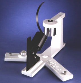
The MFR-7 consists of two basic components: a Detector Assembly and an Electronics Enclosure. The Detector Assembly consists of the MFR-7 sensor head and the stepper-motor-driven rotating shadowband, which are mounted on a common base. An electronics enclosure, mounted below the Detector Assembly, contains a YESDAS microprocessor-driven data acquisition and control system. The system electronics has 13-bit A/D conversion accuracy and has the capability of collecting data from an additional 24 analog and 6 pulse/counting-type meteorological sensors. Features
Principle of OperationThe MFR-7 uses an automated rotating shadowband to make measurements of the global and diffuse components of solar irradiance. Once these two components are known, a CPU can readily compute the direct-normal component. The geometry of the rotating shadowband instrument is shown in the figure below. The shadowband is a strip of metal formed into a circular arc and mounted along a celestial meridian with the instrument's entrance aperture at the center of the arc. The shadowband blocks a strip of sky with a 3.3° umbral angle, sufficient to block the sun. It can be positioned with an accuracy of 0.4° by the microprocessor-controlled stepper motor. The motor housing is adjusted for the latitude of the instrument. When the instrument is installed at the field site, it must be azimuthally aligned to the Earth's pole (North or South, depending on the hemisphere). Once aligned, no further mechanical adjustment is necessary and the instrument may operate for extended periods of time without any operator intervention, unlike trackers that require nearly constant attention. The operation of the instrument is controlled by its microprocessor. At each measurement interval, the microprocessor computes the solar position using an approximation for the solar ephemeris. The first measurement is made with the band rotated to its nadir position (global or total horizontal irradiance). The band is then rotated to make three more measurements. One measurement is made with the sun completely blocked (diffuse horizontal irradiance) and the other two are made with the band rotated to 9° on either side of the sun. The side measurements permit a correction for the "excess sky" that is blocked by the shadowband when the sun-blocking measurement is made. The microprocessor then subtracts the corrected diffuse component value from the global irradiance to obtain the direct-horizontal component. Finally, division of the direct- horizontal component value by the cosine of the solar zenith angle (available from the ephemeris calculation) results in the value of the direct- normal component. The entire sequence is completed in less than 10 seconds and can be programmed to occur up to 4 times per minute. The use of the computed solar ephemeris in the MFR-7 instrument gives it a significant advantage over instruments that use a continuously moving shadowband to make the global and diffuse measurements.The MFR-7 method permits much longer integration time for each measurement because it requires measurements at only four shadowband positions rather than making many measurements during a continuous scan across the sky. The longer integration time substantially improves measurement precision and permits measurements at wavelengths and passbands that would not be possible with a continuously moving shadowband. The excess sky blockage correction also significantly improves measurement accuracy, particularly under skies with fractional cloud cover. The MFR-7 has several advantages over the traditional method of using two detectors. That method requires one detector to measure the global irradiance and another detector, with a narrow field of view and mounted on a sun-tracking mechanism, to measure the direct- normal component. The MFR-7 is simpler, less expensive and more robust. In addition, the three irradiance components are derived from a single optical detector.This greatly reduces the concern about the intercalibration of the absolute and spectral sensitivity of the sensors that measure the various irradiance components. Finally, the MFR-7 instrument ensures that the measurements of the irradiance components are synchronous.
The photodiodes, interference filters, and sensitive electronic components are all held inside a temperature-controlled, desiccated enclosure. This eliminates ambient temperature-induced errors in the solar radiation data.
Control and Data Logging SystemThe MFR-7 instrument operation and data logging are controlled by a microprocessor. This on-board CPU, 1) performs the required ephemeris calculations, 2) controls the stepper motor which positions the shadowband, 3) controls the acquisition, processing and storage of sensor data for the MFR-7 and up to 24 additional analog meteorological sensors,and 4) permits simultaneous data telemetry.The ultra-stable system time-keeping (with an accuracy of 1 second per month) ensures that the positioning of the shadowband will be precise over extended time periods, with no need for operator intervention or adjustment. The system data logger includes a state-of-the-art 13 bit self-calibrating analog-to-digital converter and on-board data storage capability of up to 2 Mbytes with the PCMCIA-2 memory option. Most MFR-7 users will need the 2 Mbyte card to permit high time resolution sampling. You can communicate directly from a PC, Macintosh, or UNIX workstation through a serial port (3m cable provided) or over a phone line using a user-supplied modem. Users may download data and fully control the data acquisition process. Modem communication allows the instrument in the field to be remotely commanded from a laboratory or office without interrupting its function, making it ideal for large geographically widespread networks. Calibration FacilitiesThe usefulness of any instrument depends critically on the quality and long-term stability of its calibration. Yankee Environmental Systems, Inc. has fully equipped optical laboratories to completely characterize the performance and calibrate each MFR-7 instrument. The cosine, spectral and absolute responses of each wavelength channel of the instrument are measured with NIST-traceable optical and electronic equipment and test results are supplied with each system. Due to the nature interference filters, we recommend yearly recalibration of the MFR-7. A comprehensive document is available on our web site (under Calibration Services).
Spectral ResponseThe interference filters and photodiodes used in the MFR-7 are of the highest quality and result in an instrument with exceptional ruggedness, long term stability of calibration, and excellent unit-to-unit repeatability of response. The spectral response of each wavelength channel of the MFR-7 instrument is measured in our laboratory. Absolute ResponseThe absolute response of each wavelength channel of the MFR-7 instrument is measured using a 1,000 watt FEL NIST-traceable spectral irradiance standard light source. The spectral response of the channel and the output of the instrument in response to the irradiation by the FEL lamp are used to obtain the channel calibration constant. Cosine ResponseThe MFR-7 belongs to a class of instruments that measure flux incident on a horizontal surface. The response of such instruments to radiation incident at an angle, θ, with respect to the surface normal is called the cosine response. The ideal cosine response is proportional to the cosine of the angle θ , and any deviation from this response introduces measurement errors. The MFR-7 has a novel input optic with superb cosine response and long term stability. The radiation receiver element is a specially shaped Spectralon diffuser disk that is directly coupled to a Spectralon integrating cavity. Spectralon is a halocarbon with excellent resistance to chemical and ultraviolet degradation, thus ensuring calibration stability in the field. In addition, instruments with diffusing input optics are inherently less sensitive to surface soiling than are instruments with transmission windows such as domes.
The cosine response of each MFR-7 is fully characterized in our angular test facility. Each instrument is tested by placing it on a computer- controlled rotary actuator and measuring the instrument response as a function of its angle with respect to a feedback-stabilized, parallel, uniform light beam. The individual MFR-7 cosine response, supplied with each instrument, is used by YESDAS system software to correct, in real time, for deviations from the ideal cosine response. Instrument Development and HistoryThe Multi-Filter Rotating Shadowband Radiometer was developed for the U.S. Department of Energy (DOE) Atmospheric Radiation Measurement (ARM) program by researchers at the State University of New York at Albany and the Battelle Memorial Institute at DOE's PNNL. It was designed as a rugged field instrument to perform the required spectral measurements of solar irradiance components and to serve as the primary data logging station for a suite of associated meteorological sensors. In 1993, Yankee Environmental Systems, Inc. was granted an exclusive worldwide license by the State University of New York at Albany to manufacture the MFR-7 instrument. Also AvailableFor applications that do not require spectral information, we offer a lower cost instrument, the Single Detector Rotating Shadowband Radiometer, Model SDR-1. This instrument has only the broadband channel but is otherwise identical to the MFR-7. The SDR-1 meets the specifications for a WMO Class 1 pyranometer and, if the cosine corrections are applied, it meets the WMO secondary standard performance specifications. The broadband SDR-1 instrument measures the global, diffuse, and direct-normal components of total solar radiation making it equivalent to a total solar pyranometer and a solar tracker-mounted normal incidence pyrheliometer.
The Rotating Shadowband Photometer, Model SDP-1 is identical to the SDR-1, but contains a photopic response imitating the CIE human eye response, rather than a broadband response. A seven channel UV version with 2 nm FWHM filters, the Model UVMFR-7 is also available. The MFR-7's data acquisition and control system can be purchased separately from the instrument as the Model YESDAS-2. In this configuration, the YESDAS-2 system can collect and store data from up to 32 meteorological sensors while giving the user total flexibility in controlling the data acquisition process.
The MFR-7 is the cornerstone of the MFR line of solar radiation instrumentation; the SDR-1, UVMFR-7 and RSS-1024 are direct descendents of this technology. Installation RequirementsThe MFR-7 instrument is easy to install; it needs a user-provided level mounting platform approximately 17" in diameter. Set the latitude adjustment on the shadowband motor assembly (this is usually done at the factory). Place the Detector Assembly on a flat stable platform. Orient the instrument with the shadowband support post toward geographic north in the Northern hemisphere (south in the southern). Step-by-step instructions for this procedure are in the instrument manual. You need to perform this orientation procedure only once, at the time of installation; no further orientation adjustments are necessary. The MFR detector assembly is fabricated from anodized aluminum; all hardware is stainless steel and all connectors are potted and weatherproof. The system electronics (including the DC power supply, data acquisition board and ancillary electronics is housed in a NEMA-4X enclosure. The DC power supply is high quality a medical-grade, linear type, with a dual bobbin transformer for maximum power line transient signal and noise rejection. A 3m null modem cable is provided for direct connection with a local PC or laptop. A telephone line connection terminal with spark gap lightning arrestor is provided for connecting a user-supplied Hayes-compatible modem to the system. Screw terminal connections are provided for the 16 auxiliary sensor connections. Use the three leveling screws and the precision bubble level to position the instrument with the receiver surface in the horizontal plane. Once you have completed this step, secure the instrument to your mounting platform via a #10 screw through-hole located in the center of the base. Connect the two 2m cables from the MFR-7 system electronics enclosure to the mating receptacles on the Detector Assembly. Connect the DC standby battery and apply AC power. The MFR-7 instrument is now installed and ready to take data. You will need to provide a deep cycle marine/RV 12Vdc standby battery, as well as 115/230 Vac 50/60 Hz power to the instrument. A 2m power cord is provided (please specify desired 115 or 230 Vac when ordering the instrument.) The MFR-7 can also be configured to operate from a 12 Vdc solar panel/battery system. You must also furnish a ground rod to ensure a static discharge path independent from the path through the power grounding system to help protect against lightning.
Mechanical InterfaceSpecifications
Note: Included MFR-to-YESDAS system cables are fixed length and cannot be lengthened.
1. J. Michalsky and J. Berndt. "Automated Multifilter Rotating Shadow-band Radiometer: an Instrument for Optical Depth and Radiation Measurements." Applied Optics, Vol.33, No.22. pp 5118-5125. 2. J. Michalsky, "Objective Algorithms for the Retrieval of Optical Depths from Ground-Based Measurements." Applied Optics, Vol.33, No.22. pp 5126-5132.
|


